Acoustic shaping of imperfect shells
Using sound to sculpt defects into thin shells
Thin curved shells (a beetle's carapace, an eggshell, a pressure vessel, a rocket fairing) achieve exceptional stiffness-to-weight ratios, but that performance carries a well-known liability: their load-bearing capacity is acutely sensitive to geometric imperfections. A defect on the order of the shell thickness can trigger sudden, catastrophic buckling at a small fraction of the classical critical load. The phenomenon has resisted a clean treatment for over a century, and shells are still designed with empirical "knockdown factors" that deliberately discount the theoretical strength.
The canonical experimental approach casts desktop-scale silicone hemispheres with a deliberately introduced defect. Nearly all such work imposes a single, localized dimple, whereas the imperfections in manufactured structures are distributed across the surface in spatially extended patterns. A controlled route to shells carrying realistic, distributed imperfections has been missing.
Sculpting with sound
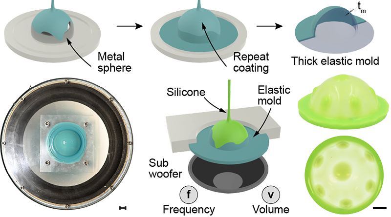
We generate these distributed patterns through forced vibration. A compliant rubber mold is first built up by repeatedly coating a metal sphere with silicone until it is thick enough to vibrate as a stiff elastic body. It is then mounted on an audio speaker and coated with a thin layer of liquid silicone. Driving the speaker at a single frequency excites a standing-wave mode of the mold, with stationary nodal lines and antinodes of maximum displacement. The uncured silicone redistributes in response, and as it crosslinks over roughly twenty minutes the resulting flow field is locked into a permanent thickness profile.
A counterintuitive flow
One might expect the high-amplitude antinodes to expel fluid; instead, silicone accumulates precisely there. The mechanism is acoustic streaming: an oscillatory flow rectifies, through nonlinear inertial effects in the boundary layer, into a steady secondary circulation (the same class of mean flow responsible for the particle migration in Chladni-plate experiments). This steady streaming transports material toward the antinodes and retains it.
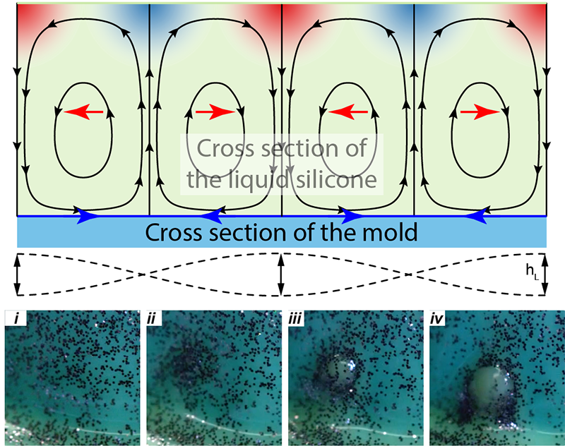
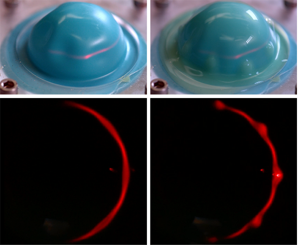
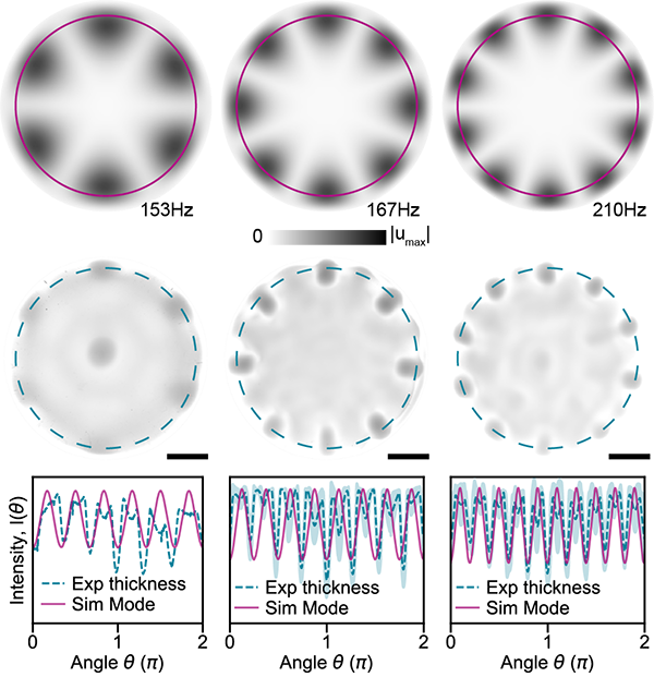
We confirmed the picture directly. Projecting a laser sheet onto the vibrating mold locates the nodes and antinodes from above, and the silicone is seen to gather exactly at the antinodes (where the vibration amplitude is largest), not the nodes.
Two control parameters
The pattern and its amplitude are governed by two independent inputs:
- Frequency selects which mode of the mold is excited, and therefore the number of antinodes: tuning the drive frequency produced shells with rings of six, eight, and ten bumps.
- Drive amplitude sets the magnitude of the imperfection, continuously scaling the deviation from a uniform thickness.
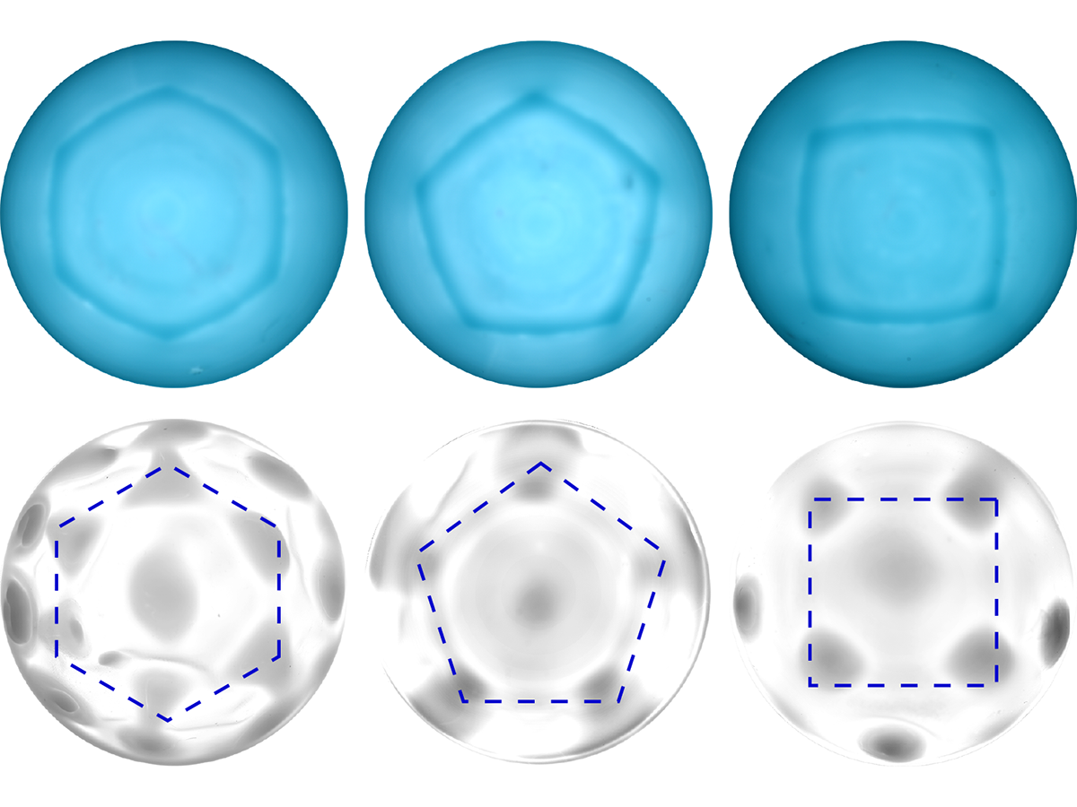
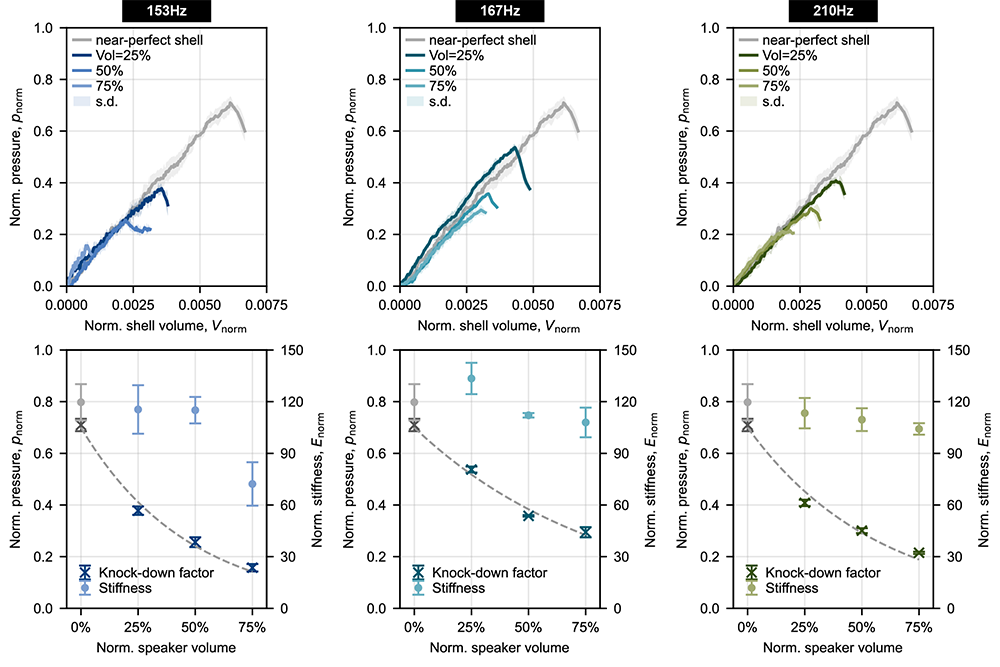
The measured thickness patterns track the finite-element mode shapes closely. At 153, 167, and 210 Hz the mold rings in modes with six, eight, and ten antinodes respectively, and the azimuthal intensity profiles of the fabricated shells match the simulated modes peak for peak.
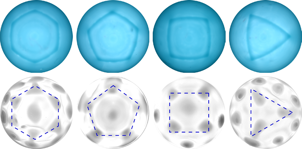
Altering the mold geometry itself accesses a broader family of patterns. Embedding triangular, square, or pentagonal protrusions in the mold makes silicone collect at the vertices, producing configurations with odd azimuthal symmetry that the axisymmetric hemisphere cannot support.
Measuring the imperfections
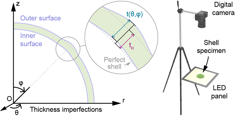
To quantify each shell we reconstruct its full thickness field photometrically: placed on an LED panel and photographed from above, the transmitted intensity at each point scales inversely with the local thickness, so a single image yields the thickness everywhere.
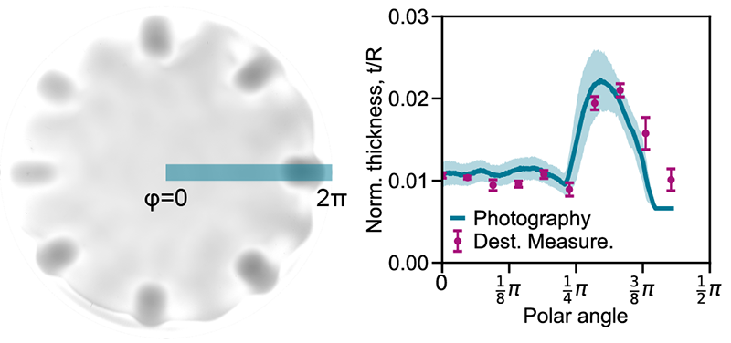
The photometric reconstruction agrees closely with destructive cross-sectional measurements and is reproducible across nominally identical samples.
Buckling
Under quasi-static vacuum loading, buckling strength decreases monotonically with imperfection amplitude. Across all three modal families, the knockdown factor falls as the drive volume (and hence the bump amplitude) increases, while the pre-buckling stiffness stays essentially unchanged. The imperfections therefore act selectively on the critical load, giving a continuously tunable handle on imperfection sensitivity that single-dimple protocols cannot provide.
Significance
The method offers shell researchers a scalable, inexpensive way to fabricate the complex, distributed imperfections characteristic of real structures, with on-demand control of their severity. More broadly, it constitutes a general strategy for patterning soft materials: by treating spatial thickness variation as a design degree of freedom rather than a flaw, the same approach can prescribe where a soft surface preferentially bends, snaps, or morphs, with applications to shape-morphing surfaces, soft robotics, and bioinspired design.
Supported by NASA MIRO (IDEAS², grant 80NSSC24M0178), the University of Houston GEAR program, and the Air Force Office of Scientific Research (FA9550-25-1-0173).
Related publications
- Vibration-assisted fabrication of thin shells with spatially distributed imperfections. Nature Communications (2026). PDF