Bistable auxetic surface structures
Flat sheets of snapping cells that deploy into a curved shape and hold it
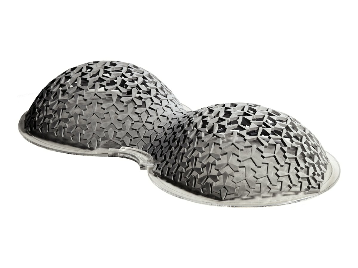
Structures that deploy from a flat state to a curved target shape reduce the cost of fabrication, transport, and construction, and in orbit or the deep sea they are often the only feasible means of erection. Conventional deployable structures use periodic patterns and reach their shape through boundary constraints, which limits the range of shapes and requires the constraints to remain in place. Systems that encode the target shape in the material instead usually need a sustained load, permanent plastic deformation, or a stimulus-responsive material and its trigger. This work introduces a third option: a sheet whose cells are individually bistable, so that the deployed surface is a local energy minimum and needs no support once it has been pushed there.
A parametric bistable cell
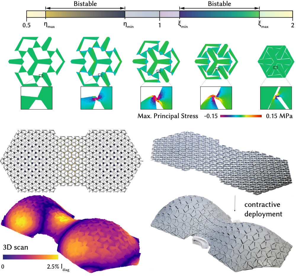
Each hexagonal cell consists of six triangular units, each defined by two parameters: a cut inclination angle and a thickness. The cell behaves as a one-degree-of-freedom linkage with a Poisson's ratio of -1, so it expands isotropically and resists every other deformation. As it expands, the inner triangles rotate and become kinematically incompatible; the compliant hinges that connect them store strain energy, which rises to a barrier and falls to a second minimum. At that minimum the force on the cell is zero and the cell is stable in its expanded state.
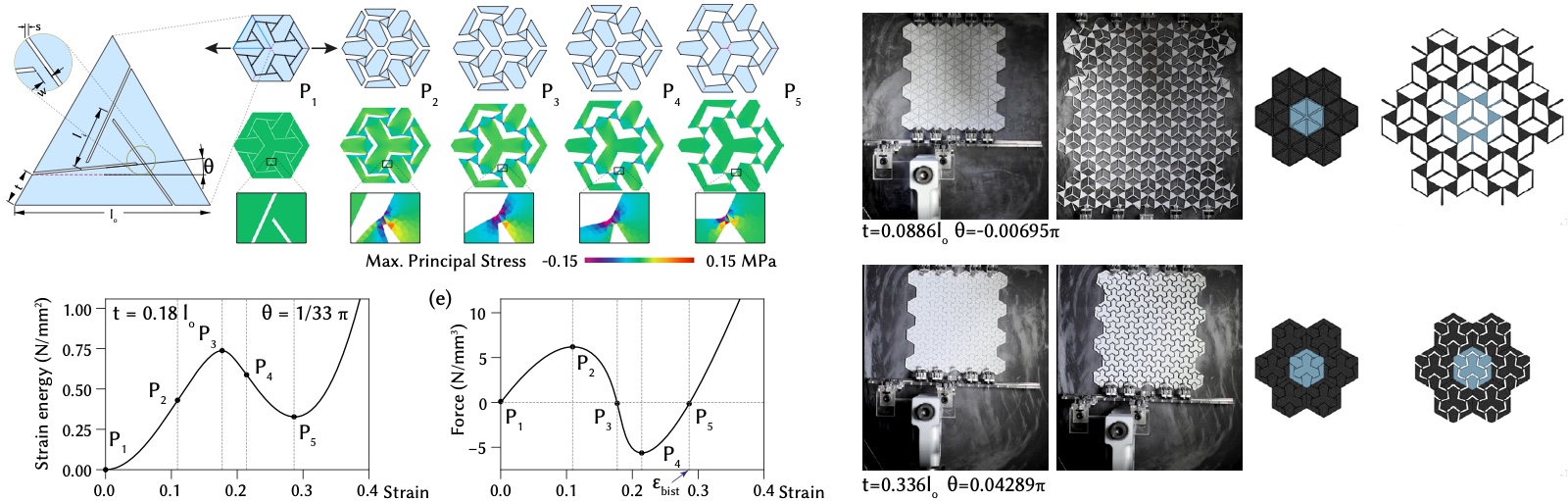
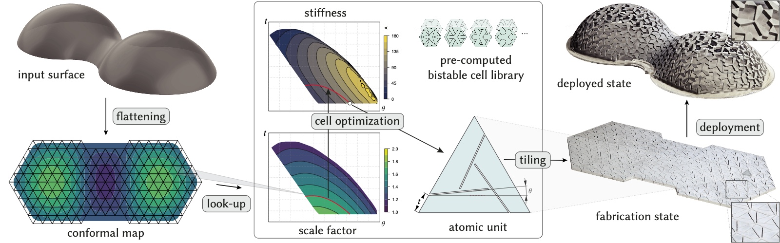
The cells are characterised by nonlinear periodic homogenisation: an infinite tiling is simulated with a plane-stress neo-Hookean model and quadratic finite elements, stretched past the analytically estimated bistable strain, then released to settle into its unconstrained second stable state, from which the expansion factor and the stiffness at that state are computed. Sweeping the two geometric parameters - 43 values of the angle, and the thickness in steps of 0.01 mm between its geometric bounds - gives a library of cells. Not every geometrically bistable cell remains bistable once hinge elasticity is included; the cells that do cover expansion factors from 1.129 to 1.775. Where several cells provide the same expansion, the stiffest is selected: the second equilibrium of a stiffer cell encodes the expansion factor more precisely, and in experiments deployment propagates as a cascade from cell to cell, so the height of the energy barrier is not the limiting property.
From target surface to cut pattern
Deployment is driven by metric frustration. The target surface is flattened to the plane with a conformal map, whose scale factor gives the in-plane expansion needed at each point to recover the surface. A regular equilateral triangular mesh of a chosen resolution is overlaid on the flattening, the scale factor is averaged over each triangle, and the library is queried for the matching cell. Where neighbouring units differ in thickness, the cut-line end points along their shared edge are averaged so that the pattern remains continuous. The result is a single flat layout whose only compatible deployed state, once every cell has snapped open, is the target shape.
Fabrication and deployment
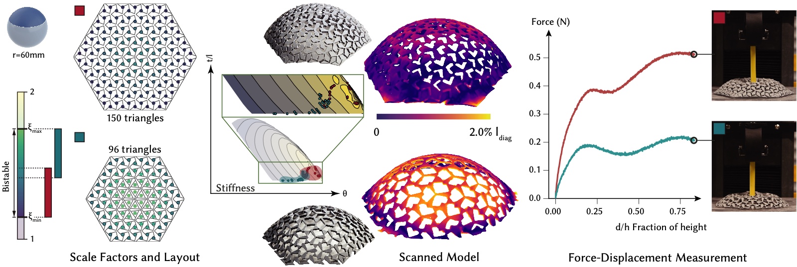
The prototypes are laser-cut from 2.3 mm rubber sheet, with a perforation width of 0.125 mm and a hinge thickness of 0.25 mm, chosen as the smallest that survives repeated opening and closing. Pushing and stretching the sheet by hand deploys it: because each cell latches, no particular order or coordination is needed, and opening some cells causes their neighbours to open. The deployed models were scanned photogrammetrically and compared with the target surface; deviations are reported as a percentage of the bounding-box diagonal and are a few percent for all models.
Steve Mould made a video of this work, filmed with the prototypes from the paper:
Beyond domes
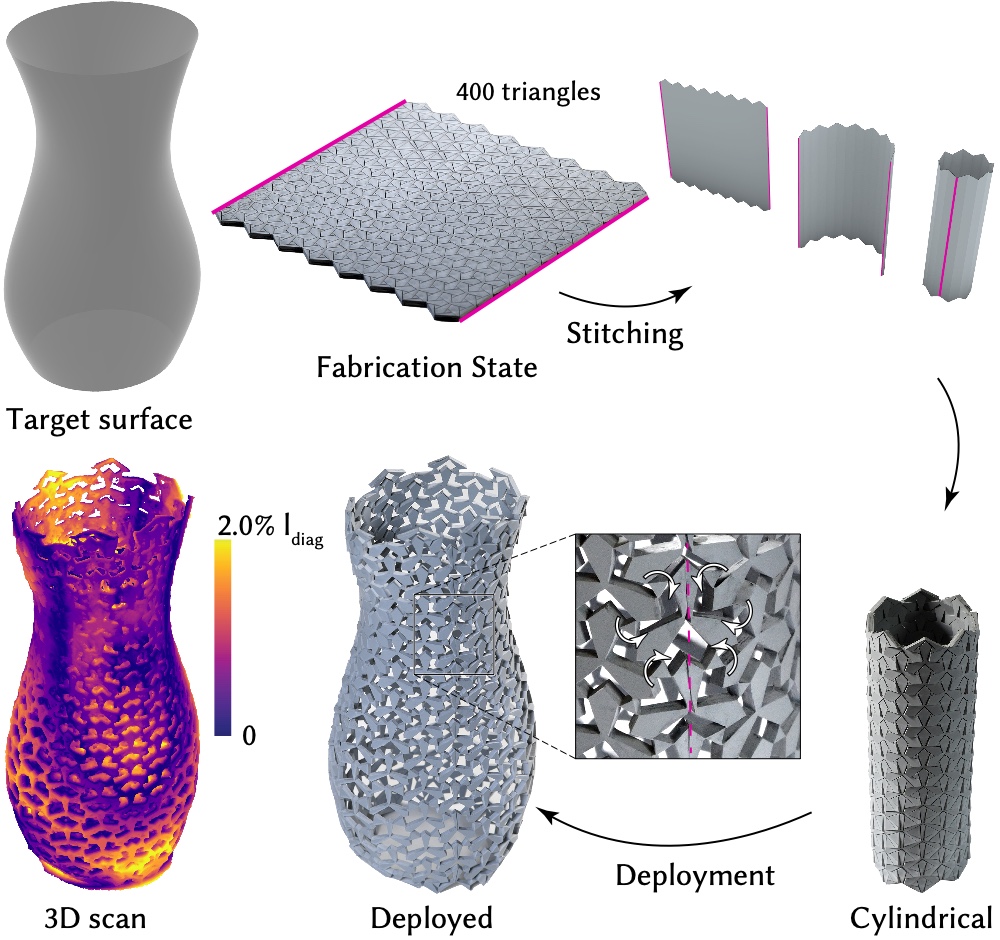
A spherical cap can be mapped to the plane with a narrow range of scale factors, so the same target can be realised from different fabrication states with different stiffness. Surfaces without disk topology are cut from one sheet with a seam: the vase below is cut flat as 400 triangular units, stitched into a cylinder along the seam, and then deployed, and the matching chirality of the units on either side of the seam lets the cells open across it.
The cells also work in reverse: fabricated open and contracting to their second state, they produce a nearly solid deployed surface at the cost of a larger flat sheet, which suits applications where the open slits would be undesirable.
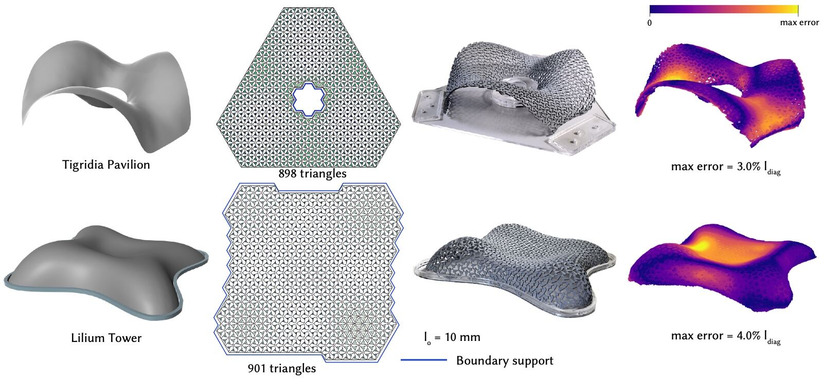
Freeform architectural surfaces show the range of the method. The Tigridia Pavilion and the Lilium Tower were realised at a cell edge length of 10 mm, with about 900 triangular units each, and their deployed shapes deviate from the target by at most 3% and 4% of the bounding-box diagonal.
Limitations
The expansion range of the cell, 1.13 to 1.78 for this material and thickness, bounds the surfaces obtainable from one sheet; more complex surfaces need singularities and seams. The metric defines the target only up to isometry, so a bump can deploy in either direction unless guided, and gravity is not accounted for in the design. The library must be recomputed for each base material and sheet thickness, since the energy barrier and the stiffness of the deployed state both scale with the material.
This work was carried out at EPFL with the Geometric Computing Laboratory and was supported by the NCCR Digital Fabrication, funded by the Swiss National Science Foundation. The same cells later became the basis of the wafer-scale deployable devices fabricated by photolithography.
Related publications
- Bistable auxetic surface structures. ACM Transactions on Graphics 40(4), 1-9 (2021). SIGGRAPH. PDF