3D-printed biaxial weaves
Mechanical characterization of woven textiles made by material jetting
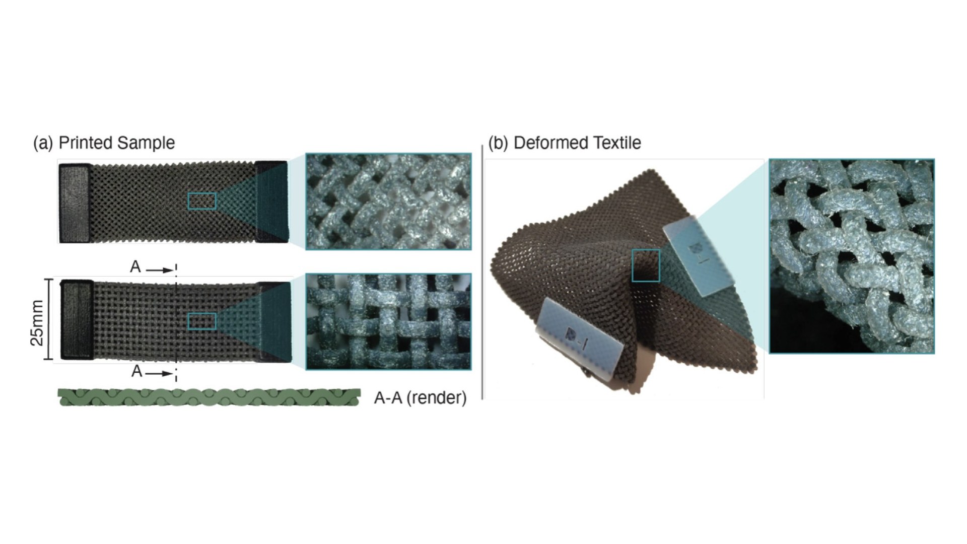
Textiles are anisotropic, pliable, and strong for their weight, and 3D printing offers a way to make them with yarn geometry that varies from point to point. Printed textiles had been demonstrated with powder-bed and extrusion processes, but their mechanical behaviour had not been characterized systematically. In this work with Marc Wirth and Kristina Shea at ETH Zurich, biaxial weaves were printed by material jetting and their tensile response was measured as a function of the weave geometry.
A parametric family of weaves
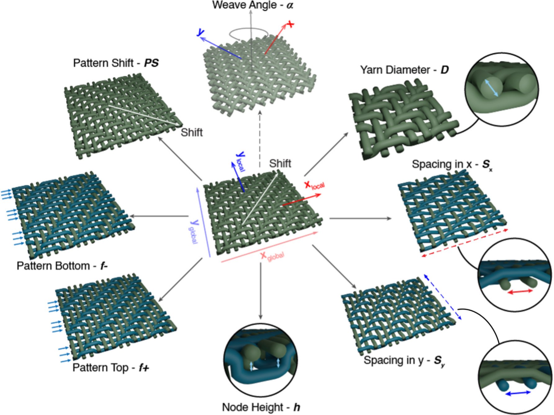
A biaxial weave is two orthogonal yarn sets and a pattern of over-and-under crossings. The design space was reduced to eight parameters: the yarn diameter, the yarn spacing in each direction, the clearance between yarns at a crossing, the pattern length on the top and on the bottom of the fabric (how many yarns a yarn crosses consecutively on each side), a pattern shift, and the weave angle between the yarns and the load. A generator places the yarn centrelines, sweeps the circular cross-section along them, and writes the surface as an STL file to a geometric tolerance of 10 µm, below the 42 µm resolution of the printer.
Printing textiles by material jetting
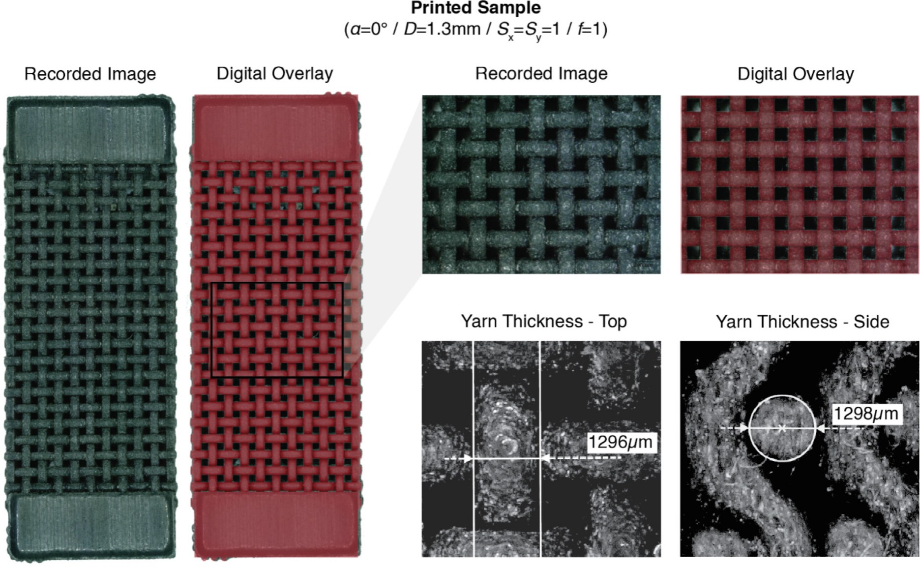
The weaves were printed on a Stratasys Objet500 Connex3 in FLX9895, a digital material blended from Agilus30 Black and VeroWhite and chosen as a compromise between the pliability and the tear resistance expected of a yarn. Layers are 30 µm thick. The fabric is printed flat, fully enclosed in dissolvable support, which is removed mechanically and in an alkaline bath. Samples are 25 mm wide and 50 mm long, following the strip test of ASTM D5035, and are printed monolithically between solid end blocks that serve as grips. Screening samples had one woven layer; the second stage used three stacked layers, 0.1 mm apart. The printed geometry matches the digital model: a 1.3 mm yarn measures 1.30 mm under the microscope.
Two-stage design of experiments
Rather than fitting a mechanical model, the response was mapped empirically, so that yarn contact, friction, and slipping are included in the measurement. Stage one is a definitive screening design: 22 runs at each of two weave angles, 44 tests in all, spanning a space of 2,916 parameter combinations. It identified the active parameters and removed the rest. The pattern shift has no effect; pattern symmetry does not matter, only the total pattern length does; and the clearance at the crossings adds a redundant nonlinearity and weakens the fabric, so it was fixed at 0.1 mm. Stage two is a full factorial design over the reduced space of yarn diameter, the two spacings, pattern length, and weave angle, 48 runs.
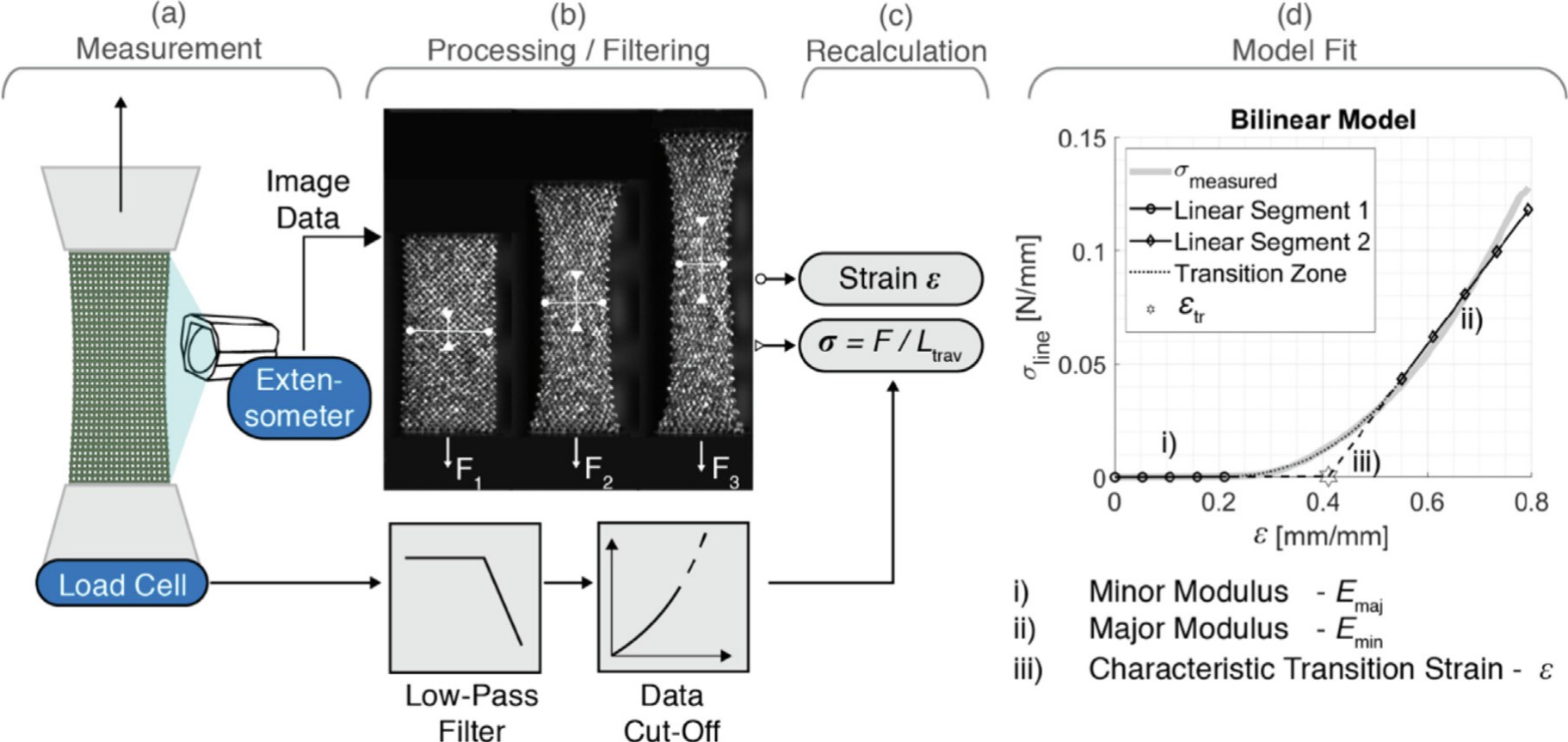
Each sample was pulled at 20 mm/min on an Instron ElectroPuls E3000, with a video extensometer tracking a speckle pattern sprayed on the fabric. Stress is reported as a line stress in N/mm, the load divided by the current sample width. Every stress-strain curve is fitted with a bilinear model joined by a quadratic transition: a minor modulus, a major modulus, and the transition strain at which the two segments meet.
What each parameter does
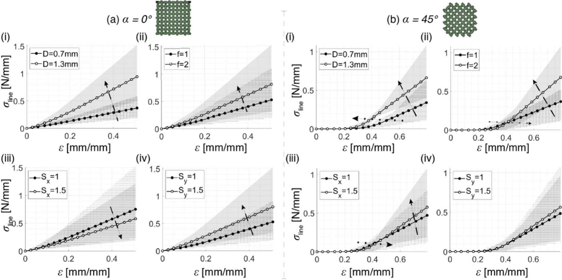
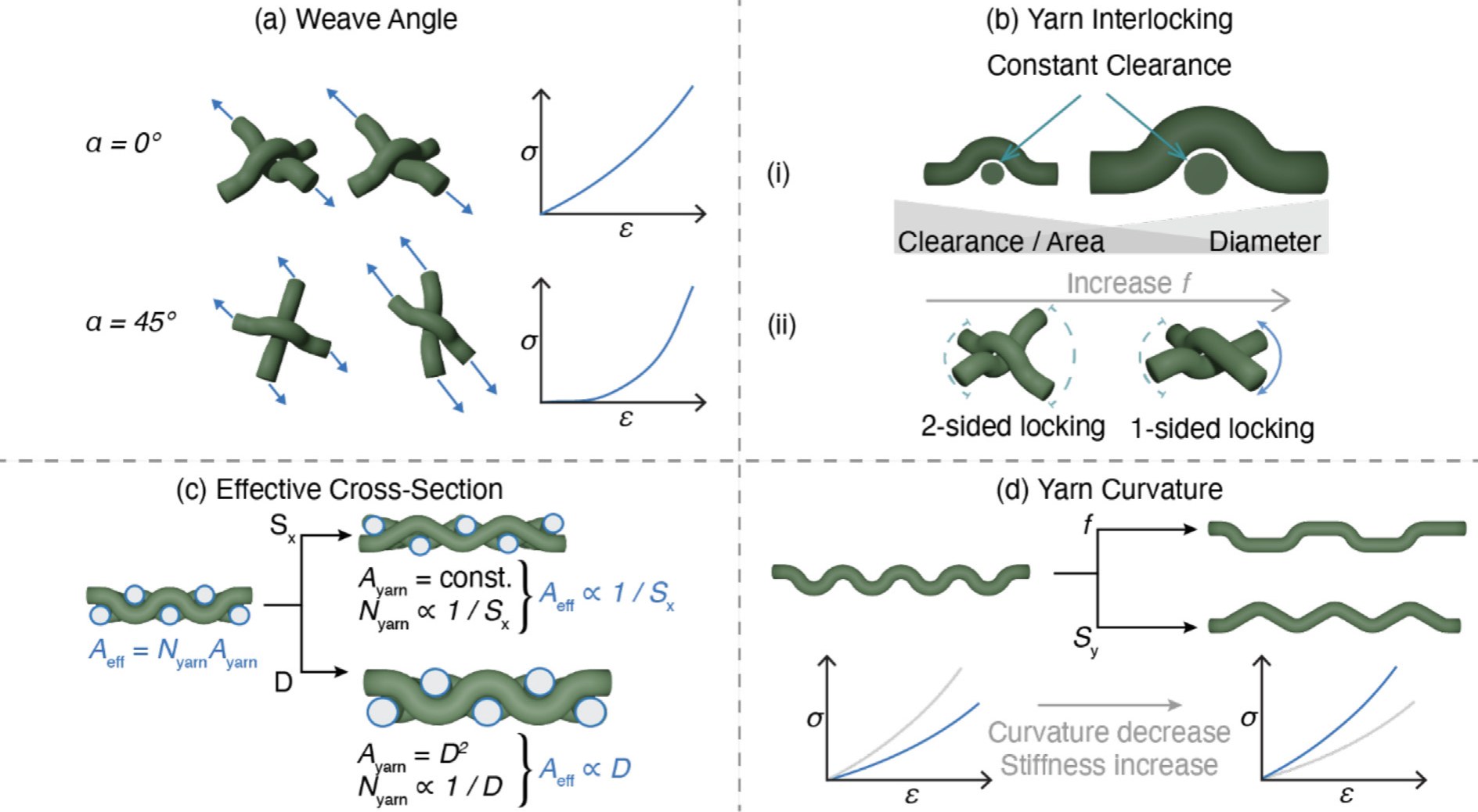
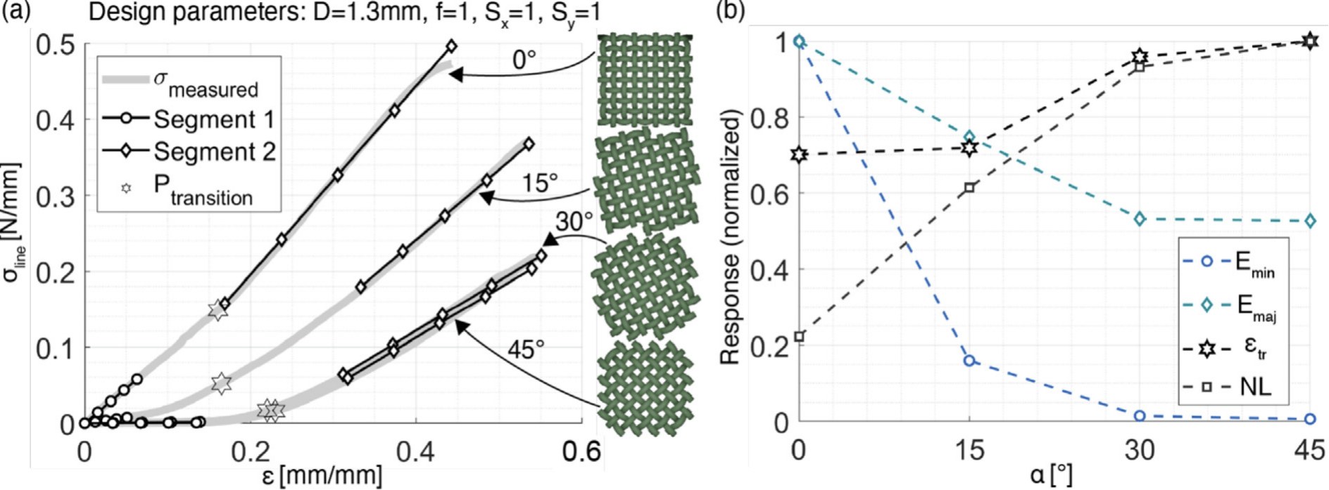
The weave angle dominates. Loaded along the yarns, the fabric responds by yarn stretching and the curve is close to linear. Loaded on the diagonal, the weave first shears like a four-bar frame with almost no resistance until the yarns lock against one another, and the response then stiffens sharply: on the diagonal the minor modulus is two orders of magnitude below the major modulus, 0.008 against 1.1 N/mm on average.
Within each mode the geometry sets the numbers. On the diagonal, yarn diameter and pattern length set when interlocking begins. Thicker yarns lock at smaller shear angles, and a longer pattern locks on one side of each node instead of two, so the transition strain rises. Along the yarns, diameter and spacing set the effective cross-section, and pattern length and spacing set the waviness of the yarn, and with it how much of the load is carried by bending before the yarn is taut.
Poisson's ratio and intermediate angles
On the diagonal the Poisson's ratio follows the kinematics of the shearing frame, rising from 1 to a peak near the transition strain and then falling to between 0.3 and 0.5 once the yarns lock. Along the yarns it settles near 0.1. Samples cut at 15° and 30° lie between the two limiting cases, but not in proportion to the angle: the diagonal behaviour persists for angles close to 45°, because there only interlocked yarns can transmit load.
Fracture across the print layers
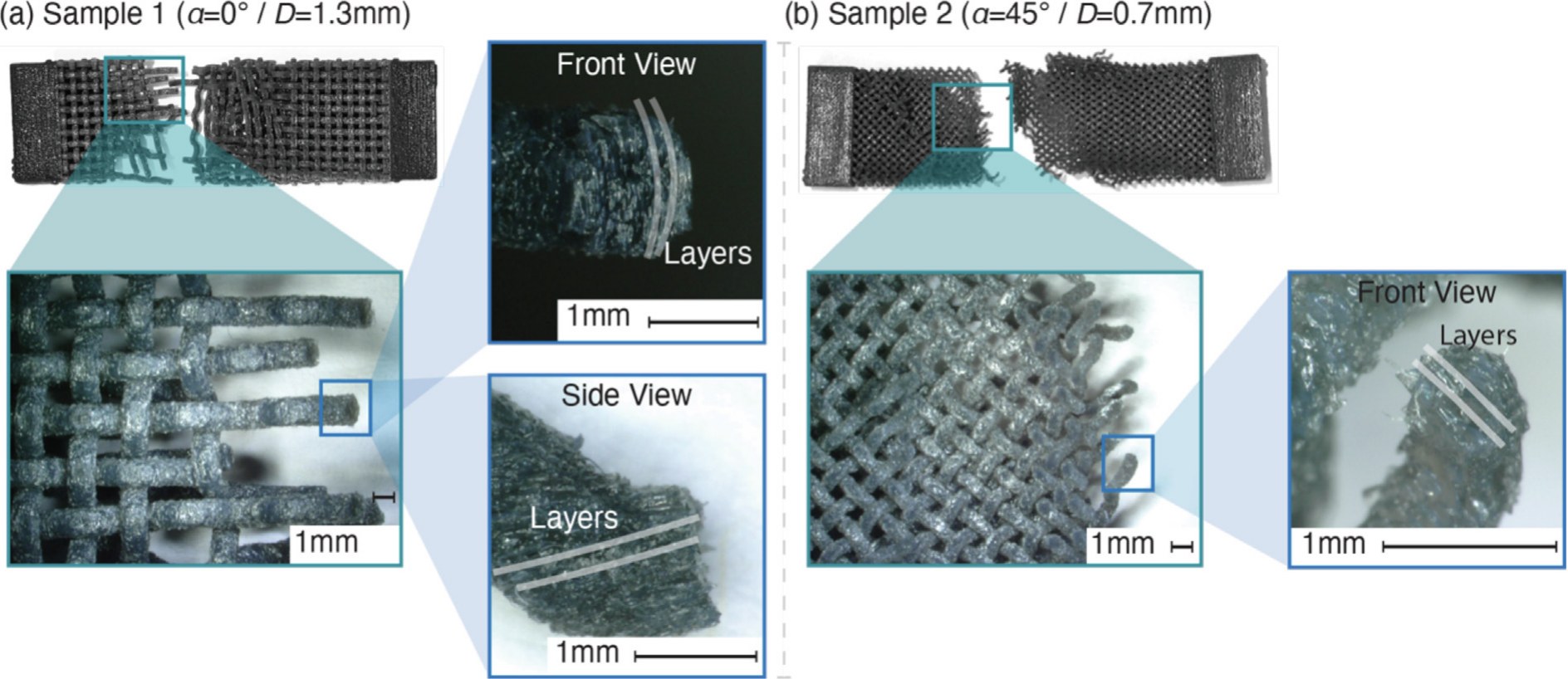
Extruded 3D-printed textiles fail by delamination between print layers. In the material-jetted weaves the layers are visible in the fracture surfaces, but the tear runs perpendicular to them: the yarn fails as a material, not as a stack. A printed textile can therefore be laid out in any in-plane orientation without regard to the print direction.
Beyond loom-made fabric
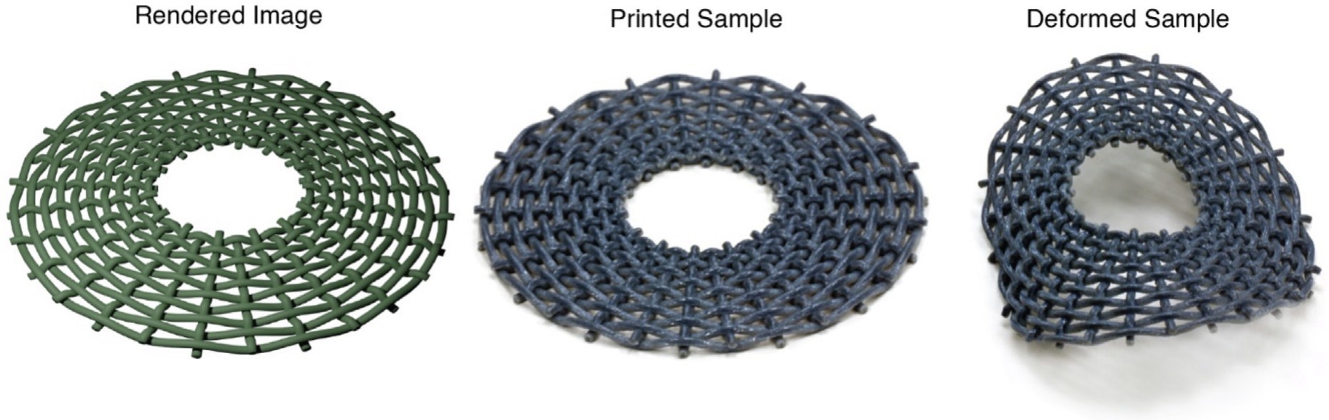
Because the parameters describe the geometry at each crossing, the measured responses can be assigned node by node to build models of textiles whose mechanical properties vary across a patch, for example in wearables. The same freedom extends to geometries no loom produces: the ring below has closed circumferential yarns and prints without seams. The group's later work on 3D-printed knits continues this line.
Related publications
- 3D-printing textiles: multi-stage mechanical characterization of additively manufactured biaxial weaves. Materials & Design 225, 111449 (2023). PDF